
Help
Drawing a Layout
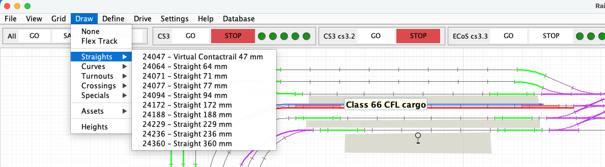
The Draw menu changes the canvas from normal operation into a specialised drawing mode. It provides track from the active catalogue together with flextrack, assets, signals and tools for defining height.
Enter and leave drawing mode
Choose any drawing item to place the canvas in the corresponding drawing mode. Other menus are temporarily unavailable so that clicks on the canvas cannot accidentally start an unrelated operation. Choose None, the first entry in the Draw menu, to leave drawing mode and return the canvas to normal selection and operation.
Place catalogue track
Choose a track article and move the pointer over the canvas. Click to place the proposed track. RailKernel uses the connectors defined by the catalogue to attach new track to compatible open connectors and to preserve exact geometry. Continue placing copies of the selected article, or choose another article or None when finished.
Flextrack and the Bézier curve
Flextrack connects two selected open track connectors when no fixed catalogue article provides the required geometry. RailKernel constructs a cubic Bézier curve between the two endpoints. The endpoints determine where the flextrack connects, while the direction of each connector determines the tangent of the curve at that end. The two Bézier control points then create a smooth transition that leaves and enters the adjoining track in the correct direction. Because flextrack is part of the layout graph, its calculated length, connectivity and endpoint heights participate in blocks and routing just like catalogue track.
How the Draw menu is filled
The track sections of the Draw menu are rebuilt from the active project catalogue. RailKernel groups the available definitions as straights, curves, turnouts, crossings, specials and other elements. Every entry therefore represents an article and geometry definition from that catalogue; changing the active catalogue changes the articles offered by the menu. Imported or special-purpose definitions may be sorted below the ordinary track articles.
Why a catalogue can contain virtual rail
A virtual rail represents a logical part of the physical railway for which no separate manufactured article exists. For example, one physical contact rail may need to be represented as two shorter logical sections so that the exact feedback boundary, train position and braking distance can be modelled. The virtual pieces exist only in the RailKernel project: they do not imply that the physical rail must be cut or replaced. Their accurate length and connectors let blocks, feedbacks and routing describe the real railway correctly.
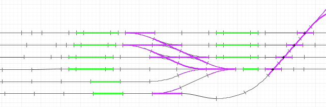
Instead of defining one 24995, place two virtual 24047 rails. You can then add one adjoining 24027 rail to the feedback section when required. This accurately defines the detected length, whereas half of a 24995 cannot be added to a feedback.
Preview, snapping and rotation
Before placement, RailKernel draws a preview at the proposed position. The preview shows whether the article will snap to an open connector and lets you inspect its orientation before committing it. When more than one placement or orientation is possible, right-click to rotate or cycle through the available placement proposals. Left-click only when the preview shows the intended connection.
Assets and buildings
The Assets submenu contains non-track objects such as buildings. These objects enrich the visual layout without becoming railway edges in the routing graph. Select an asset, define its position and size on the canvas, and finish the placement as indicated by the drawing cursor. Assets can later be selected and edited independently from the track beneath them.
Signals
Signals are also placed from the Assets submenu. A signal is an operational object associated with a position on the layout and, where configured, with a command-station address and signal definition. Place it where its meaning is clear to the operator; its visual position does not replace the block, route and accessory definitions that determine automatic driving.
Heights and slopes
RailKernel creates vertical geometry by defining slopes rather than moving an entire section to one arbitrary level. Choose Heights and select the start and end of the sloping path, then specify the required height transition. RailKernel distributes the change along the connected track so that intermediate connector heights and gradients remain consistent. Because track pieces have a height at both ends, level track has equal endpoint heights while a slope has different endpoint heights. These values are used to show levels and to calculate realistic route length and gradient information.
Check the result
After drawing, choose None and inspect the layout in normal mode. Open connectors indicate incomplete geometry; Project Statistics can also identify open or unreachable elements. Correct these structural problems before generating blocks or relying on automatic route search.